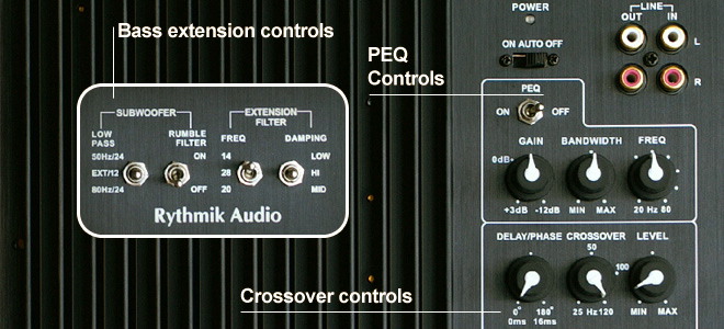
Parametric EQ controls
The toggle switch on the top can switch the single band of parametric EQ on or off. Below this is the gain setting on the left. The gain level is from 3 dB to -12 dB. The bandwidth controls how wide the notch/peak is. The frequency knob on the right controls the center frequency. It can be set from 20 Hz to 80 Hz with each dot position representing a 10 Hz increment. Boost below 40 Hz is not recommended. Above this point, our subwoofers have greater headroom.
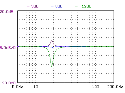
Fig 1.0 - PEQ gain settings
The first plot below is the gain control at 3 different positions: 3db, 0db, and -12db. The frequency setting is at 20hz. The bandwidth is at min.
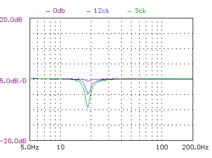
Fig 1.1 - PEQ control
In terms of sensitivity, the 12 o'clock position gives us about -5db attenuation while 3 o'clock position gives us -10db attenuation. In other words, the range between 0db and 3 o'clock is what we will use most.
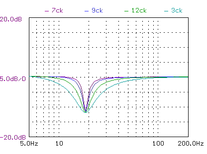
Fig 1.2 - PEQ width control
The comparison is between 7 o'clock, then 9, 12, and 3. Please note that 5 o'clock hasn't been plotted as it is same as 3 o'clock position. The gain is at -12db and frequency is set to 20 hz.
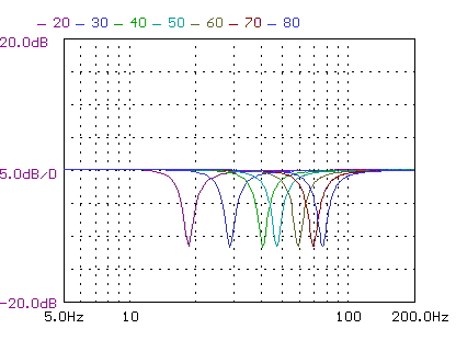
Fig 1.3 - PEQ center frequency setting
Next is the frequency setting comparison at various dotted positions, from 20hz to 80hz. Please note that the labels do not correspond exactly to the actual setting.
Crossover controls
Crossover controls include phase control on the left, then crossover setting in the middle and gain on the right.
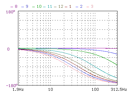
Fig 1.4 - Variable phase control setting
The phase control has been improved in resolution and labels have been adjusted to be more accurate. The circuit is a simple RC all pass filter. A similar circuit is used for adding delay time (such as those in Linkwitz's all active speakers). While the circuit does provide delay, it is limited to 180 degrees. Theoretically, given a fixed delay, the phase shift should be proportional to frequency. However, this RC circuit will not go beyond 180 degrees.
Bass extension and management controls
The two switches on the left control bass management and the rumble filter. The two switches on the right are our bass extension controls which are standard on all our amplifiers, and control how low the bass response will extend.
For users with a home theater receiver using the receiver for bass management: select 12 db/AVR (middle position). AVR means the main crossover is external. In this case, the crossover control knob is mainly for fine tuning.
For users not using bass management: select either 50hz/24 or 80hz/24. 50hz/24 means the plate amp implement a low pass filter with a fixed 12db at 50hz, plus the 12db adjustable knob to make up a 24db total slope. Similarly for 80hz/24. The following shows the frequency response of this 50hz and 80hz fixed filter.
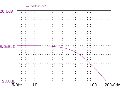
Fig 1.5 - 50Hz/24 setting
A fixed 12 dB slope is used at 50 Hz. A variable 12 db/octave filter is also provided. When the variable slope is set also at 50 Hz, a combined slope of 24 db/octave is achieved.
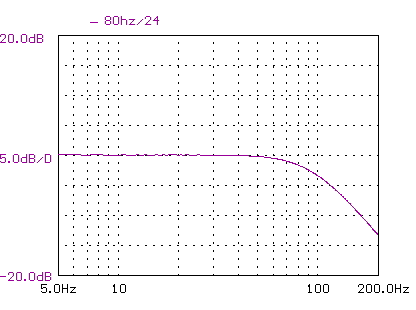
Fig 1.6 - 80Hz/24 setting
A fixed 12 dB slope is used at 80 Hz. A variable 12 db/octave filter is also provided. When the variable slope is set also at 80 Hz, a combined slope of 24 db/octave is achieved.
In either case, one should always use the crossover knob in the middle to fine tune the overlap between subwoofer and front speakers. It is more important to combine this control and phase control to achieve the best results.
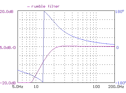
Fig 1.7 - Rumble filter
Response and phase of the rumble filter. The rumble filter is has a 3rd order slope (18 db/octave) fixed at 20 Hz.
The rumble filter is useful in particular for vinyl use and in home theater applications where high output is desired. The driver is protected from over excursion resulting from high amplitude subsonic content.
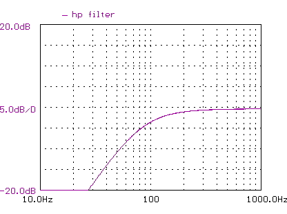
Fig 1.8 - High pass filter on line out
Response and phase of the high pass filter on the line out. One can use this output to give the main speakers bass filtering. The output is sent to the power amplifier used for the main speakers.
XLR model
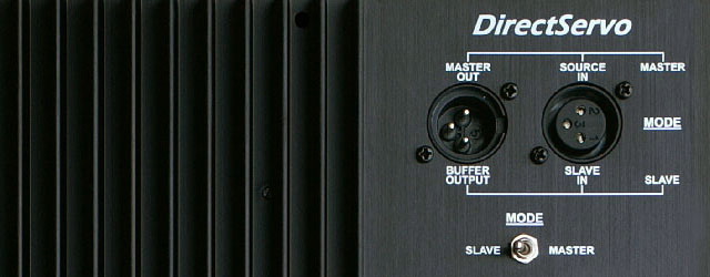
The settings on our studio balanced version are the same except for the inputs.
Single subwoofer use: Connect input to "source in" and set mode to master.
Multiple subwoofer use: Connect the master subwoofer with master mode selected. The controls on that amplifier will be used for the other slave subwoofers. Connect the master out to the slave input of the other slave subwoofers. Set slave subwoofers to slave mode. All other settings on the slave amplifiers will be by passed.
