There has been some feedback that protection circuits of A300/A370 amplifiers are a little bit too sensitive for low frequency rumble signals (below 14hz). Since those amplifiers have been very reliable in the field, we feel it is safe to relax the SOA protection a little bit so customers can enjoy the movies better without interruption. In the following, we describe the procedure to replace C10 on the power amplifier board from 4.7uF to 10uF/35 BP cap to relax the SOA protection.
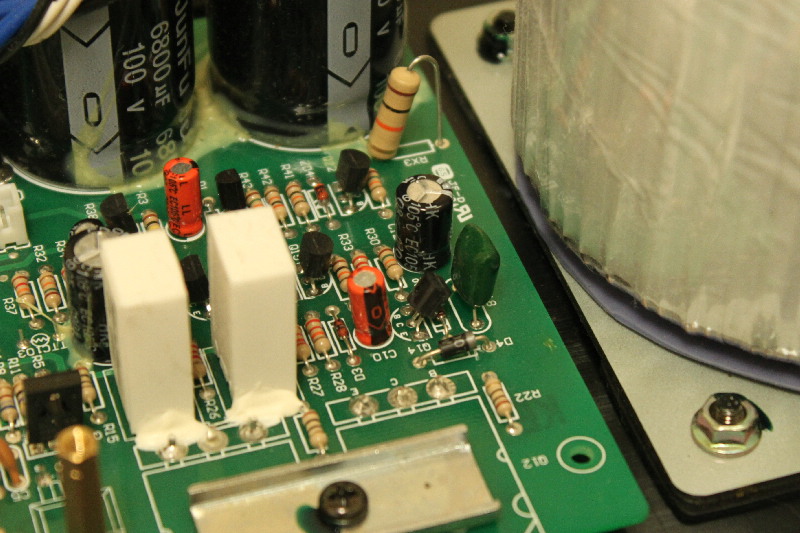
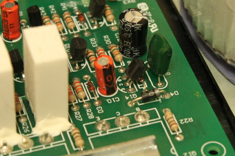
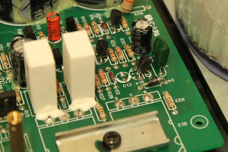
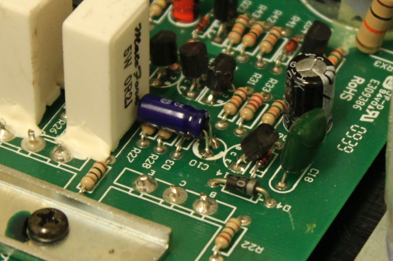
First we show the general area and the close-up shot of C10 (orange color cap).
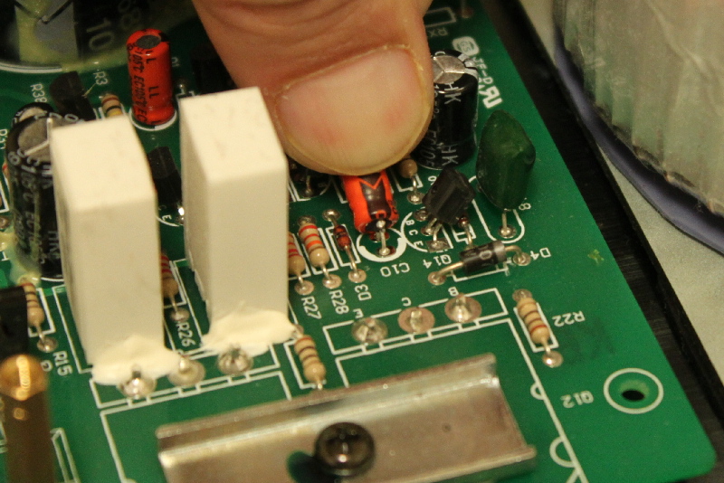
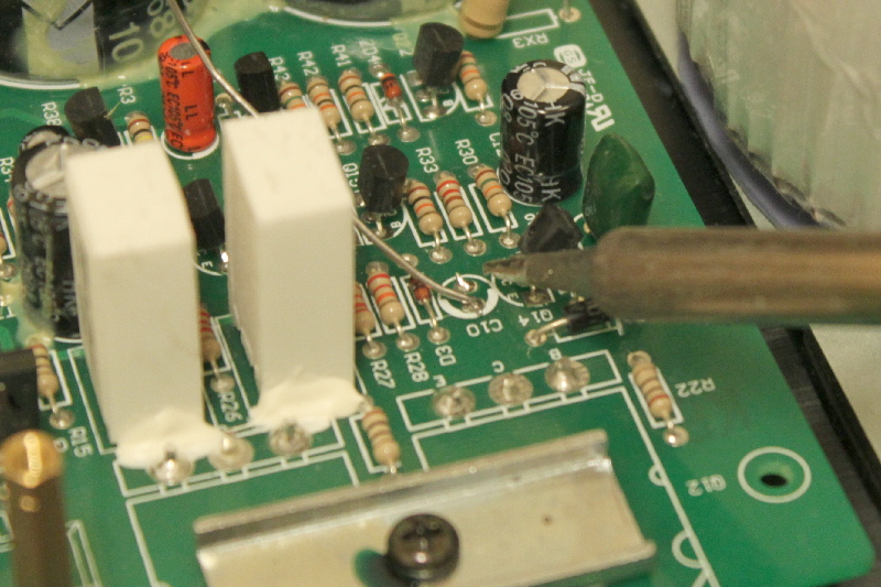
Before we do anything, it is a good idea to push Q14 away from C10 so we have more space. Don't push it too hard. To remove C10, we need to push the cap sideways to expose the leads underneath it. Since we will destroy C10 anyway, one can push a bit harder. After the wires are exposed, use wire cutter to cut the leads and remove C10.
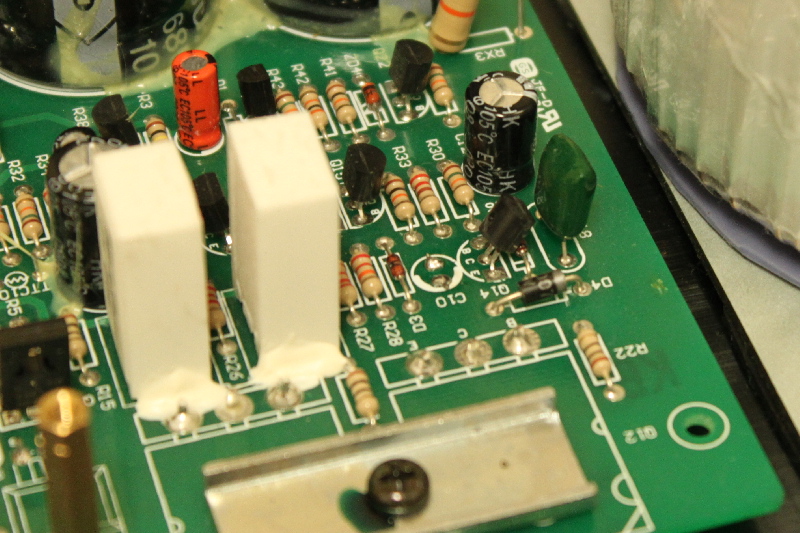
After the C10 is cut out, the remaining leads are sticking out. The reason that we want to keep some remaining leads is to prevent them from dropping through the holes when we melt the solder later on.
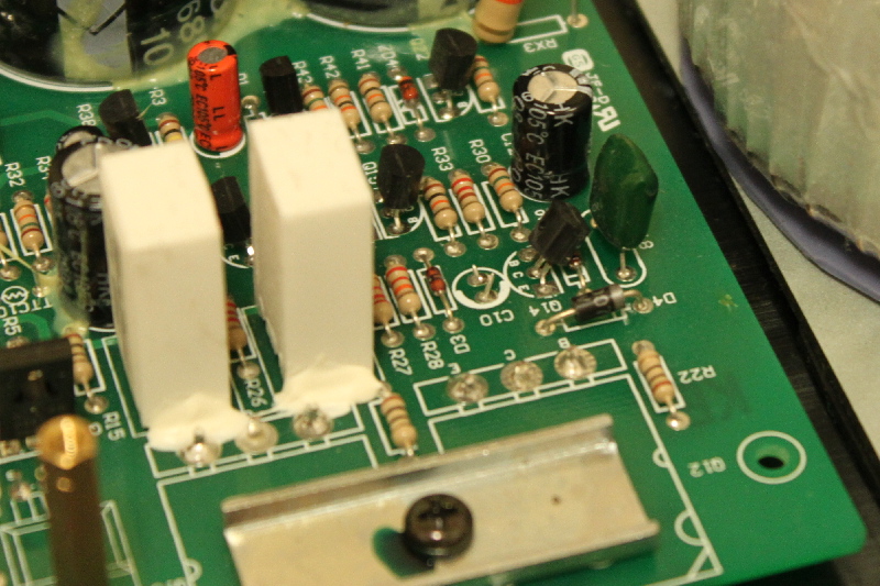
We need to push the remaining leads down and outward so that they don't touch each other and they don't touch anything else as follows.
Next we need to add solder to both solder pads as follows.
In the following is what the solder pads of C10 will look like after we add solder to both of them.
Next we are ready to add the cap. Here is the cap that we supply.
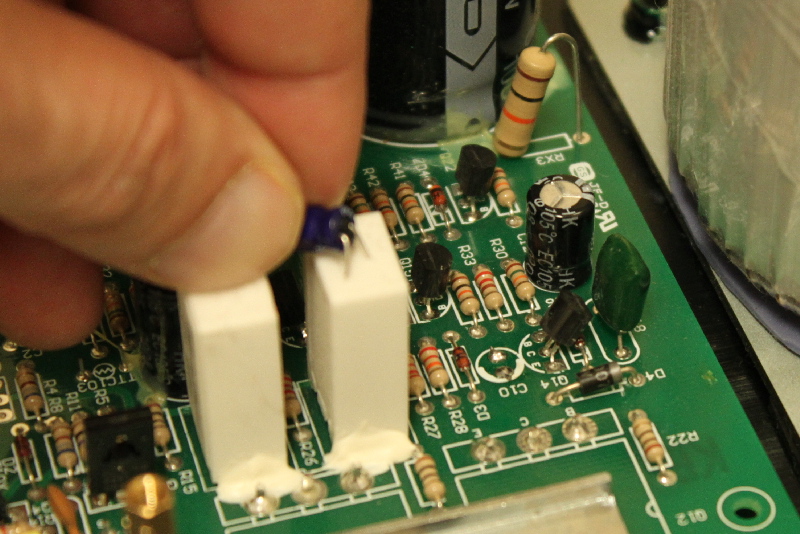
Next we need to solder the cap to C10 location and the sideways view after we are done is as follows.
The last step which is not shown on the photo is to put a small amount of silicone glue between the cap and the big "5W 0R2J" resistor to avoid any vibration.